
Voice Controlled Prosthetic Hand
I started SRIP as an intern under Prof. Madhu Vadali at Tinkerer's lab, IITGN on 17 May, 2025. The objective was to build a voice controlled prosthetic arm with my partner, Kshitij Giri (IITGN B.Tech'27), which has now been completed. This article documents the process of building the arm and discusses the results.
The arm's base structure is from the InMoov open source 3D printable robot. This arm was modified by other designers to convert it into a wearable prosthetic. We tweaked it further to add Bluetooth connection with a smartphone, so one can get minimum latency between speech and action.
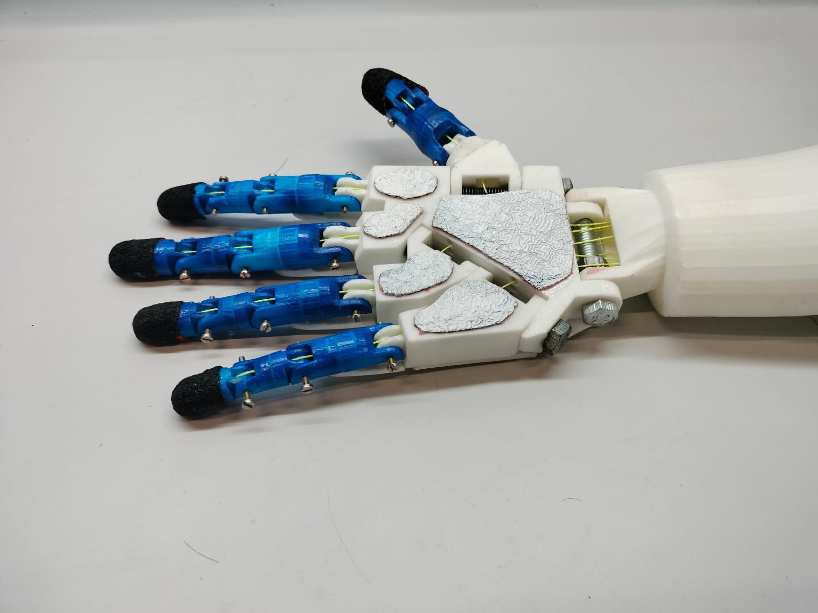
The parts of the arm were 3D printed with PLA, and then assembled. Assembly was done using bolts to give freedom of movement to all places where joints would be in a human hand. However, in this hand, the wrist only has one degree of rotation, and the thumb has one plane of movement as well. Nevertheless, the fingers had enough movement to reliably grip most objects.
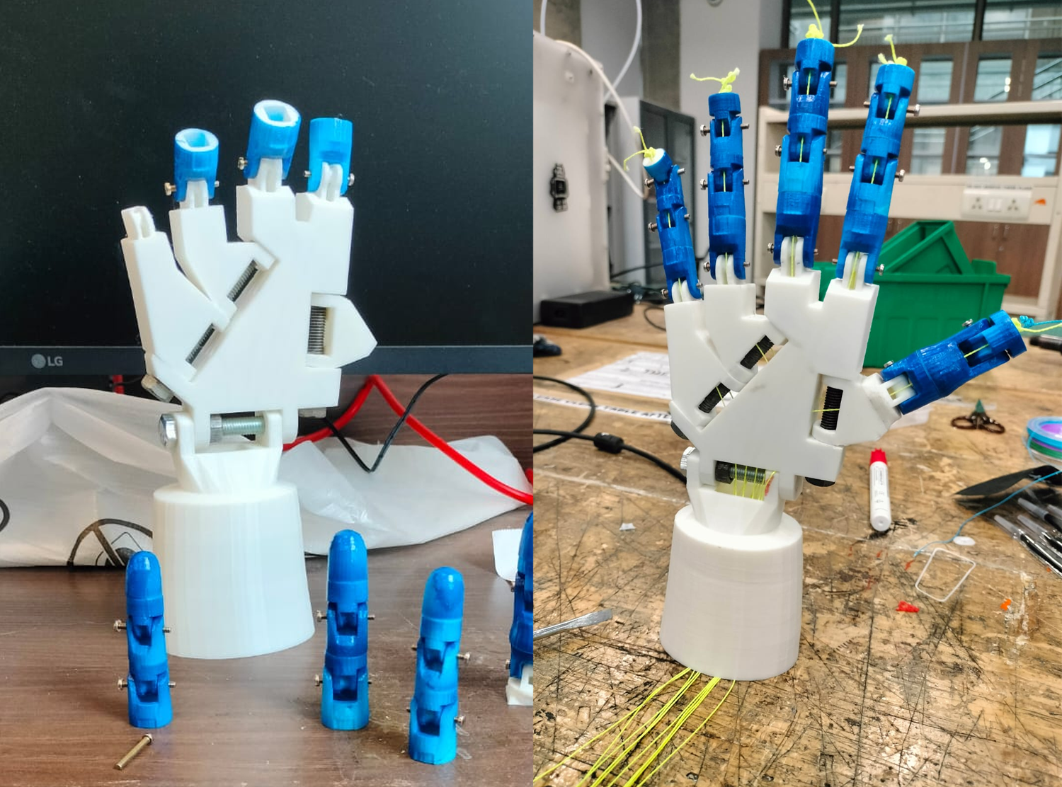
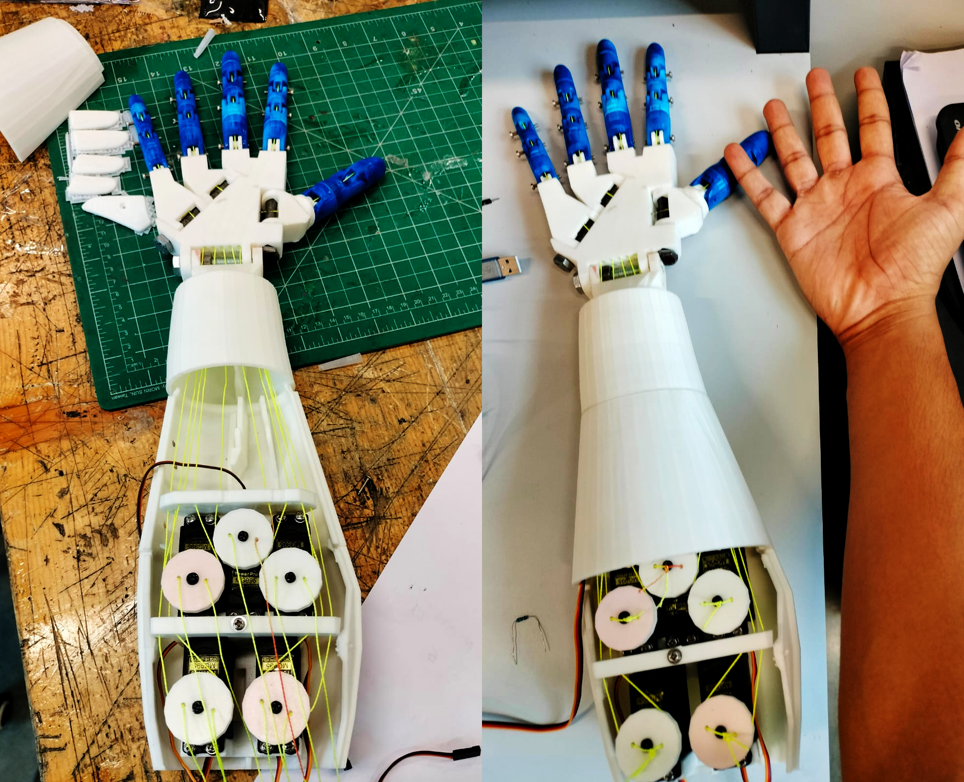
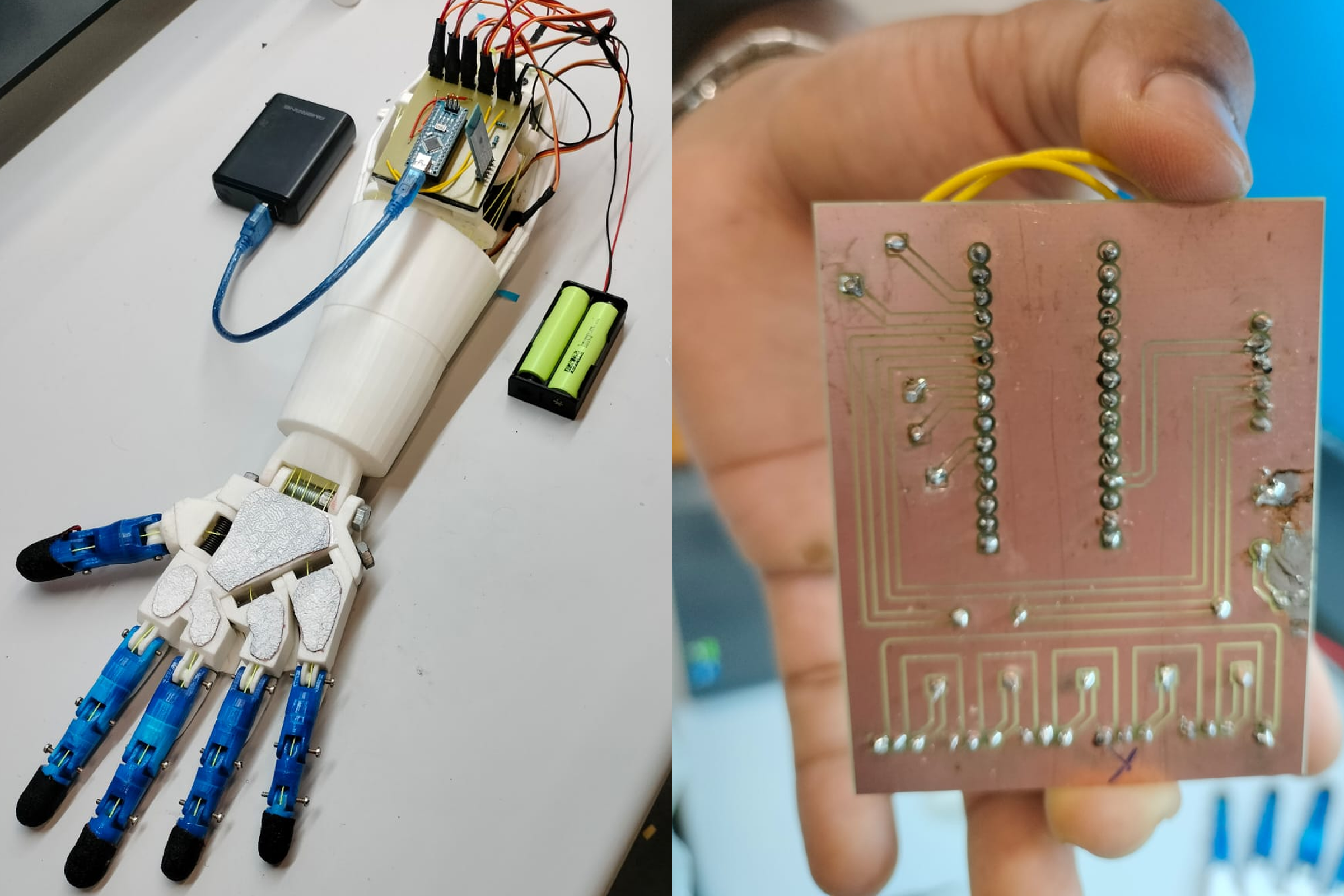
The fingers were threaded with fishing wire. The fishing wire is the "muscles" of the hand. Each finger has 2 corresponding wires, one for flexion and another for relaxation. These finger wires are connected to MG995 Servo motors, which are attatched to a bed inside the forearm. In hindsight, it would have been much better to use steel wire instead of the nylon fishing line that we used, because over time, with tension, the nylon wire generates some slack and has to be regularly retightened, atleast for a few weeks.
The MG995 motor bed was powered with 7.4 volts from Li batteries. The commands for these motors were given through an Arduino Uno in the initial days of development, and later, an Arduino Nano. The Arduino was programmed to contain preset rotation values for all motors, which correspond to different finger positions. These positions could be set through serial input, or later, Bluetooth via a cellphone. The presets include - Neutral, Grab, Call, Rock, Type, Pencil, Flick, Thumb, Point and Test.
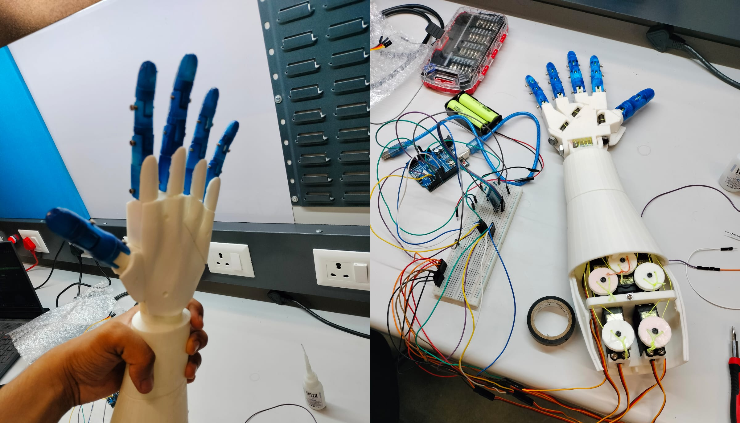
At this point, were were powering the motors using the battery and the Arduino through a Laptop, while everything was connected to a breadboard. The next step was to get free from USB input and add voice commands. We tried using an Elechouse voice recognition module with the Arduino Uno, but it was too inefficient at recognising words, and took a long time to decode. Because other Arduino - compatible options were exhorbitantly priced, we decided to go with the smart microphone that everyone carries around - a smartphone. We used an HC-05 Bluetooth module to connect to the mobile phone, and gave serial inputs through the phone's built in Speech to Text.
Because the arduino was now free from USB input, we tried to power it through the batteries directly through it's VCC pin. But, the arduino became slow, as it internally stepped down the voltage to 4.3 volts. So, we settled on using a power bank to power the arduino for the time being.
The mess in these images is truly a reflection of our minds while working on this project. :P
Anyways, we had to do something about the absolute hairball of wires that was slowly getting bigger over time. To tackle this, we decided to print a circuit board, which would look clean, organised and professional. We designed the PCB and milled it from copper. Having all the elements in the PCB at one place without the mess of wires, and having the power, neutral and signal wires of the servo motors so neatly organised took the hand to the next level.
One of the motors decided that our lives were going just a bit too smoothly and decided to stop operating. We had to disassemble quite a lot of the hand just to get that motor out. Learning from this, we made some changes to the original InMoov design to make the motor bed more accessible. Also, we made a mount for the PCB, attatched with Velcro, so it's completely removable.
Finally, we had to power the Arduino using the battery source. Since the direct method of powering through Vcc was out of the question, we decided to use a buck converter and a USB adapter to power the Arduino. This way, the arduino got sufficient power without needing a separate power source.
And just like that, we were almost done! The hand totally worked and could grip and lift objects as well. We decided to make a battery holder which was flush with the body of the hand to have an elegant solution to house the power source.
The video doesn't demonstrate all the functions, but there we have it, that's the hand. Also here is the battery holder that we made. This battery holder was made in Blender, by using the difference modifier. I never knew learning Blender would prove to be useful in engineering.
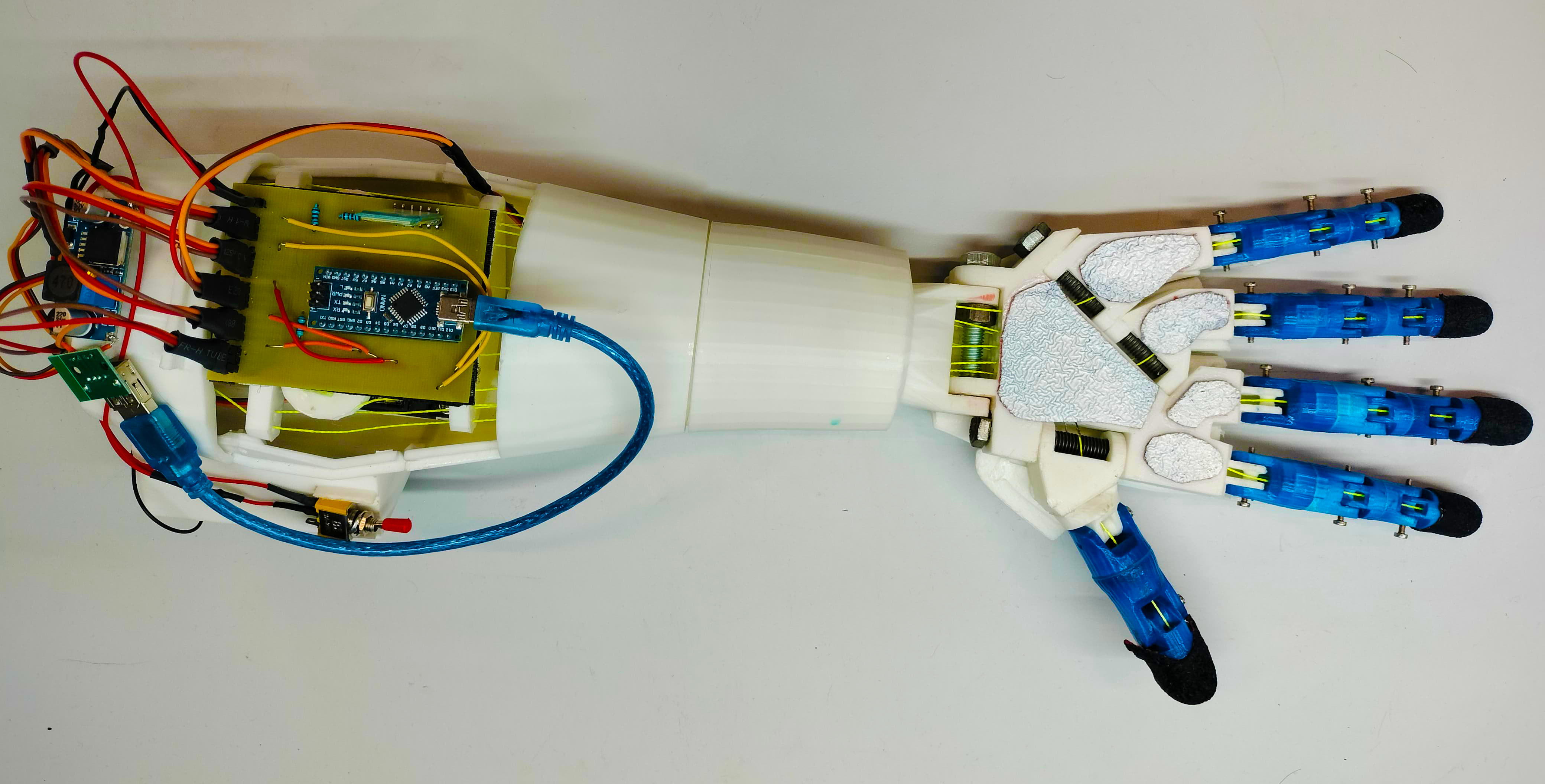
There it is. The complete prosthetic hand. We are also currently working on a quadcopter, so I will soon post another article about it. Hopefully it goes well.